Printed Circuit Boards (PCBs) are the backbone of modern electronic devices, acting as a platform for connecting and supporting various electronic components. An efficient and well-structuredPCBlayout is crucial for ensuring optimal performance, signal integrity, and reliability of electronic devices. In this comprehensive guide, we will explore the essential aspects of PCB layout design, from the basics to advanced guidelines and helpful tips.
Table of Contents
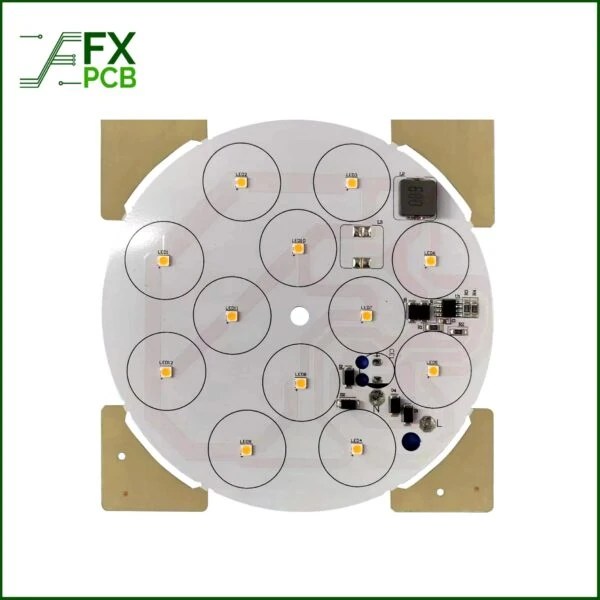
Our Recommended LED Light PCB

Light PCB assembly is the process of assembling and soldering electronic components onto a printed circuit board (PCB) to form a functional electronic device. The PCB material should be chosen based on factors like fire retardant, dielectric constant, loss factor, tensile stability, glass transition temperature, and Z-axis expansion coefficient. Common materials used for Light PCBs are CEM-1, CEM-3, FR-4, aluminum, and copper alloys. The material should be selected based on the specific requirements of the electronic device being produced.
Shenzhen PCB assembly manufacturer is the ideal place for your Light PCB assembly needs. We can assist you in assembling everything from industrial high-power LEDs to commercial flood LEDs.
Free Make an Inquiry
Understanding PCB Layout Design:
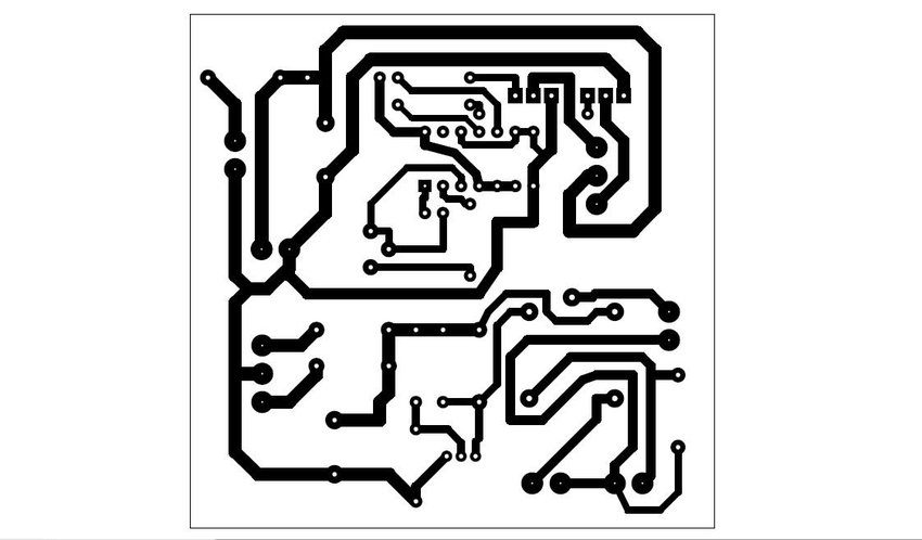
PCB layout design is the process of arranging electronic components, conductive traces, power planes, and other elements on a circuit board to facilitate the flow of electrical signals and meet the functional requirements of the electronic system. The layout design is a critical step in the PCB design process, as it directly impacts the electrical performance, electromagnetic interference, thermal management, and manufacturability of the final product.
Designing a PCB (Printed Circuit Board) layout can seem intimidating at first, but with the right tools and understanding of the process, it becomes more manageable. Here’s a general guide to help you design a PCB layout:
Schematic Design: Start by creating a schematic diagram of your circuit. This will help you plan the connections between components and understand the overall layout of your PCB.
Choose PCB Design Software: Select a PCB design software that suits your needs and level of expertise. Some popular options include Altium Designer, Eagle, KiCad, and OrCAD. These tools offer various features for schematic capture, PCB layout, and design verification.
Component Placement: Import the components from your schematic into the PCB design software. Arrange them on the board to optimize signal flow, reduce trace lengths, and ensure proper clearances between components.
Routing Traces: Connect the components using traces (copper lines) on the PCB. Consider the current-carrying capacity, signal integrity, and noise immunity when routing traces. Keep traces short and direct to minimize signal interference.
Power and Ground Planes: For better noise reduction and improved power distribution, allocate separate power and ground planes. Connect all ground points to the ground plane to create a low impedance return path for current.
Signal Integrity: Check for signal integrity issues such as reflections and crosstalk. Use controlled impedance traces for high-speed signals to maintain signal integrity.
Design Rules Check (DRC): Perform a design rules check to ensure that your layout complies with the fabrication capabilities of your PCB manufacturer. The DRC will catch errors like trace width violations, clearance violations, and other manufacturing-related issues.
Thermal Considerations: If your circuit generates significant heat,design the PCB layoutwith proper heat dissipation in mind. Use thermal vias and heatsinks as necessary.
Silkscreen and Documentation: Add component designators, reference labels, and any other important information to the silkscreen layer for easy assembly and debugging.
Design Verification: Before sending your design for manufacturing, perform thorough design verification. Use tools within your PCB software to check for errors and simulate the circuit’s performance if needed.
Gerber Files Generation: Generate the Gerber files, which are the standard format used by PCB manufacturers to fabricate the PCB.
Manufacturing: Choose a reputable PCB manufacturer and submit your Gerber files along with any other required documentation. Review the manufacturer’s guidelines and requirements to ensure a successful fabrication process.
Assembly: Once you receive the fabricated PCBs, you can assemble the components yourself or use a PCB assembly service.
PCB Layout Basics:
Before delving into advanced concepts, let’s cover the fundamental components of a PCB layout:
a. Layers:
PCBs are often designed with multiple layers to accommodate complex circuitry. Common layers include top and bottom copper layers, power and ground planes, and signal layers. Each layer serves a specific purpose in the overall functionality of the PCB.
b. Components:
Electronic components, such as resistors, capacitors, integrated circuits (ICs), and connectors, are placed strategically on the PCB to ensure efficient signal flow and minimize signal distortion. Proper component placement also helps in thermal dissipation and ease of assembly.
c. Traces and Vias:
Traces are conductive pathways that connect various components on the PCB. Vias are plated holes used to establish electrical connections between different layers of the PCB.
d. Power Planes:
Dedicated copper planes are used for distributing power and ground throughout the PCB. These planes help in noise reduction and provide a stable power supply to the components.
PCB Layout Design Process:
The PCB layout design process typically involves the following steps:
a. Schematic Design:
The circuit schematic is the initial representation of the circuit’s electrical connections and components. It serves as a blueprint for the subsequent PCB layout design.
b. Component Placement:
During this stage, designers strategically place the components on the PCB to optimize signal flow, minimize trace length, and ensure efficient thermal management.
c. Routing:
The routing process involves creating conductive pathways (traces) between components to establish electrical connections. Proper routing techniques are essential to avoid signal interference and crosstalk.
d. Design Rule Check (DRC):
After completing the layout, designers perform a DRC using PCB design software. The DRC verifies that the layout complies with manufacturing and design rules, such as trace width, spacing, and clearance requirements.
e. Gerber Generation:
Once the layout is verified, designers generate Gerber files, which are industry-standard files used by PCB manufacturers to fabricate the board.

PCB Layout Tips:
Designing an efficient PCB layout requires attention to detail and adherence to best practices. Here are some valuable tips for creating a successful PCB layout:
a. Component Placement Optimization:
Group related components together and place high-speed components closer to each other and the power source to minimize signal delays and noise.
b. Signal Traces and Routing:
Pay attention to trace width and impedance control for signal integrity. Separate high-speed and low-speed signal traces to reduce interference.
c. Thermal Considerations:
Optimize thermal dissipation by placing components with high heat dissipation needs close to thermal vias or heat sinks.
d. Ground Plane Design:
Utilize dedicated ground planes to improve noise immunity and reduce ground loops.
e. Design Rule Checks (DRCs):
Regularly perform DRCs to identify and rectify layout errors, ensuring compliance with design specifications.
f. Manufacturer Collaboration:
Engage with the PCB fabrication house early in the design process to understand their capabilities and avoid potential manufacturing issues [2].
PCB Layout Guidelines:
To ensure a successful PCB layout, follow these essential guidelines:
a. Component Orientation:
Keep component orientations consistent to facilitate ease of assembly.
b. Trace Width and Spacing:
Use appropriate trace widths and spacing to handle current-carrying capacity and impedance control.
c. Power Plane Design:
Implement proper power plane structures for distributing power efficiently and minimizing voltage drops.
d. Signal Integrity and High-Speed Design:
Employ signal integrity techniques for high-speed signal routing to prevent signal degradation and reflections.
e. Silkscreen and Assembly Markings:
Provide clear silkscreen markings and assembly indicators for proper component placement during assembly.
Pcb layout software
Altium Designer: Altium Designer is a widely-used PCB design software known for its intuitive user interface, powerful features, and extensive component libraries. It offers tools for schematic capture, PCB layout, 3D visualization, signal integrity analysis, and manufacturing file generation.
Cadence Allegro PCB Designer: Cadence Allegro is a professional-grade PCB design tool commonly used in the industry. It provides advanced features for high-speed PCB design, differential pair routing, constraint-driven layout, and collaboration between team members.
Eagle PCB: Eagle PCB is a user-friendly PCB design software suitable for hobbyists and small projects. It offers a free version for limited designs and a paid version with extended features, such as multilayer board support and larger board sizes.
KiCad: KiCad is an open-source PCB design software that has gained popularity among hobbyists and small businesses. It provides a suite of tools for schematic capture, PCB layout, 3D visualization, and extensive community support.
OrCAD PCB Designer: OrCAD PCB Designer, developed by Cadence, is a comprehensive PCB layout tool with features like constraint-driven routing, powerful signal and power integrity analysis, and seamless integration with other tools in the OrCAD suite.
PADS (Mentor Graphics): PADS is a powerful PCB design software tailored for medium to large-scale design projects. It offers a scalable platform with various levels of functionality, making it suitable for both beginners and advanced PCB designers.
Proteus PCB Design: Proteus PCB Design is a user-friendly software that combines schematic capture, simulation, and PCB layout in a single package. It is often favored by hobbyists and students for its ease of use.
DipTrace: DipTrace is a versatile PCB design tool suitable for projects of different sizes. It offers an intuitive interface, 3D modeling, a vast component library, and extensive manufacturing file support.
EasyEDA: EasyEDA is an online PCB design tool that allows users to design and share PCB layouts directly in a web browser. It offers schematic capture, PCB layout, and cloud-based collaboration features.
DesignSpark PCB: DesignSpark PCB is a free, entry-level PCB design software developed by RS Components. It provides a user-friendly interface and basic PCB design capabilities.
Conclusion:
Awell-designed PCBlayout is integral to the success of any electronic device. Understanding the basics, following best practices, and incorporating design guidelines are essential for creating efficient, reliable, and manufacturable circuit board layouts. By combining technical expertise, attention to detail, and collaboration with experienced PCB manufacturers, designers can develop cutting-edge electronic products that meet the demands of today’s technology-driven world. Remember, continuous learning and staying updated with the latest advancements in PCB design tools and techniques will further enhance the quality of PCB layouts and contribute to the development of innovative electronic products.

Peter Gong
I am Peter Gong. I have been working in PCB and PCBA industry for 15+ years now. I have been a part of the PCB revolution with my dedication to circuit board technologies and creative ideas. I write in FX PCB to impart my knowledge on PCB and PCBA for all circuit board lovers, manufacturers, and users.
Our Recommended Products for You
Ceramic PCB AIO203 Material 3
Ceramic PCB 16
Aluminum Nitride PCB Manufacturer in China
Ceramic PCB 14
Ceramic PCB 13
Ceramic PCB 12
check out all products